Edit a workflow
The editor and the canvas
The workflow is designed in the Editor tab, which opens at the end of the creation wizard or when opening an existing workflow from the Workflows dashboard.
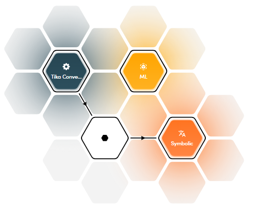
The central part of the editor is a canvas: the workflow corresponds to the diagram you compose inside the canvas.
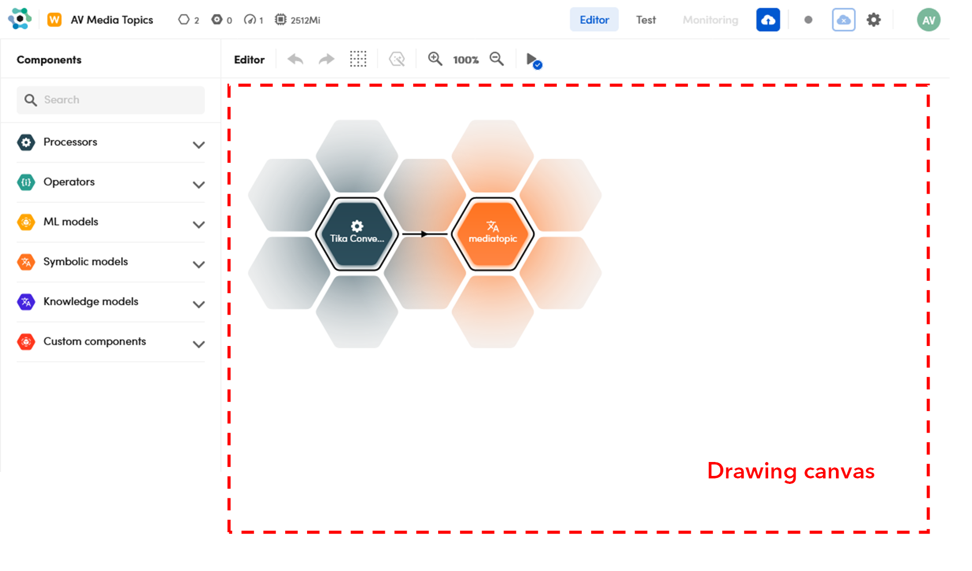
The canvas is a grid composed of hexagonal areas that reveals itself when you hover over it as you add or move blocks. All the blocks and connectors snap to this grid.
Components
The left panel, Components, shows the blocks you can choose from to compose the workflow.
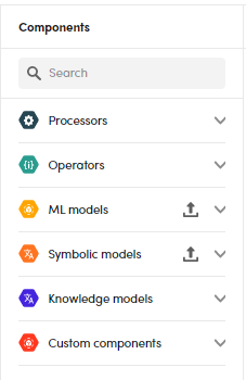
Components types are:
- Processors
- Operators
- Symbolic and ML models
- Knowledge models
- Custom components
Symbolic and ML models may have been previously published from Platform authoring application or uploaded from the Models view of the main dashboard.
Knowledge Models are built-in models. Custom components are installation or customer specific components.
The flow
Each workflow has a processing direction that goes from left to right, so place the blocks along the same direction. To create the flow you connect blocks: a connection means that, at runtime, the outptut of the left block will "flow" to the right block.
Typically a workflow consists of a single flow of blocks connected to each other, but it is possible, in the same workflow, to draw multiple unconnected flows. In this case, the first block of all the flows receives the same input and the overall output of the workflow is the concatenation of those of all the flows.
However it is also possible to have the overall output from a block placed in any part of the workflow. In fact in the Test tab it is available a specific filter option.
Add blocks
To add a block to the workflow:
-
Select the corresponding component from the left menu: a grid of dashed hexagons is displayed and shows the locations where you can place the block.
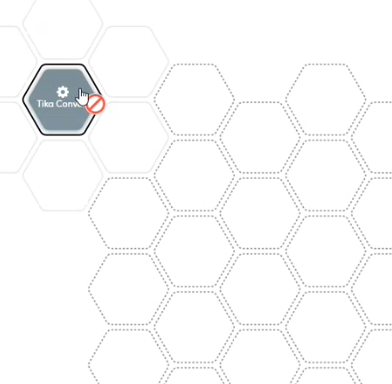
The "no passing" sign
 appears if you try to place the block in a position that is not allowed.
 -
Place or drag the block over a dotted hexagonal shape.
Info
A block corresponding to a model that:
- Was created with the Platform authoring application using the Pdf document view to annotate extractions.
Or:
- Was created with expert.ai Studio and relies on document layout information (because, for example, has rules that use the
TITLELEVELattribute).
must be preceded by an Extract converter block.
Warning
If NL Flow determines that input mapping is needed, a dashed line is drawn around the block and a warning message is displayed.
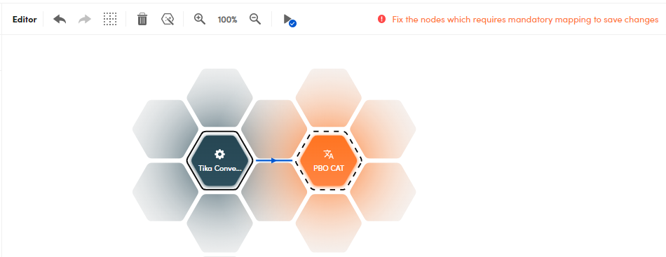
Input mapping is done by editing the block and setting its input properties. Read the pages in reference section to know more about the input properties of models and processors.
Remove blocks
To remove a block, select it in the canvas and:
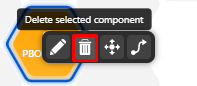
- Right-click and select Delete selected component
 on the context menu.
Or:
- Select Delete selected component
 on the canvas toolbar.
Move blocks
To move a block, select it in the canvas and then:
- Right-click and select Move selected component
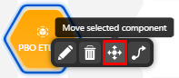 on the context menu, then move the block to the new position and click to release it.
Or:
- Select Move selected component
 on the canvas toolbar, then move the block to the new position and click to release it.
You cannot place a block adjacent to another, the "no passing" sign appears if you try to place the block in a position that is not allowed.
Connect blocks
Add and remove linear connectors
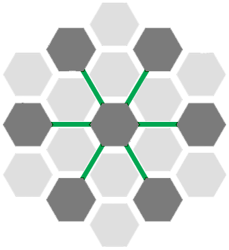
Use the linear connector to connect two blocks that are within one segment of each other.
To add a linear connector between two blocks:
-
Select the white space corresponding to the ray shared by the two blocks.

Or:
- Right-click the first block and select Connect selected component
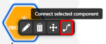 on the context menu, then select the second block.
Or:
- Select the first block.
- Select Connect selected component
 on the canvas toolbar.
 - Select the second block.
Each linear connector has an arrow that reminds you of the flow direction (from left to right).
-
To remove a linear connector, select it, then:
- Press the
Delkey.
Or:
- Select Delete selected component on the canvas toolbar.
- Press the
Add and remove junctions
Linear connectors cannot be linked one to another, so, for longer paths, use junctions.
A junction is both a (inactive) component and a multiple connector. The junction component is represented by a white hexagon with a small black hexagon at the center.
-
To add a junction, just select the empty hexagon at the end of a linear connector.
-
To remove a junction, just select it. Selecting a hexagon at the end of a linear connector—when not already occupied by an active component—then acts as a toggle switch to add or remove a junction.
Edit a block
To edit the properties of a block:
- Right-click the block and select Edit component
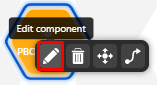 on the context menu.
Or:
- Double-click the block.
Or:
- Select the block, then select Edit component
 on the canvas toolbar.
In the reference section of this manual you will find the description of the editable properties for model blocks, processor blocks and operator blocks.
Info
Hover over a block to display component name and version.

Undo and redo changes
To undo or redo a change, select Undo  or Redo
  respectively on the canvas toolbar.
Save changes
To save changes, select Save on the canvas toolbar.
Validate the workflow
To validate the workflow, select Validate current workflow  on the canvas toolbar.
Info
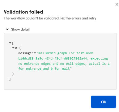
If the validation fails, the Validate current workflow icon shows a red alert sign  and the Validation failed dialog is displayed. Expand Show detail to know more aboute the errors.
Clear the canvas
To clear the canvas, select Clear workflow  on the drawing area toolbar.
Warning
If you clear the canvas, all your changes are lost, so save changes frequently.
Optimize layout
- To optimize the blocks position in the canvas, select Optimize layout
 on the canvas toolbar.
Zoom
To enlarge and reduce the diagram select Zoom in  and Zoom out
  .
.
Workflow info
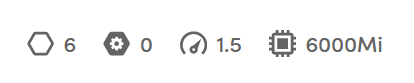
The left part of the toolbar displays information about the workflow, in particular:
- Number of blocks
- Number of JavaScript blocks
- CPU load
- Memory load
Each time you modify and save the workflow the information are updated.
Define the input format
When:
- A workflow starts with more blocks of different types (for example a URL converter processor and a Tika converter processor) and the input to the workflow is going to be a JSON with separate top level keys that must be "divided" between the starting blocks.
Or:
- The workflow input is a JSON with top level keys that conceptually correspond to top level keys "recognized" by workflow blocks, but with non standard names.
the formal definition of the workflow input allows specifying the name and the type of the top level keys of the input JSON. The keys can then be mapped to the input of workflow blocks—no matter their position in the flow—by editing the block and setting its input properties to the keys of the $nlflow_input pseudo block.
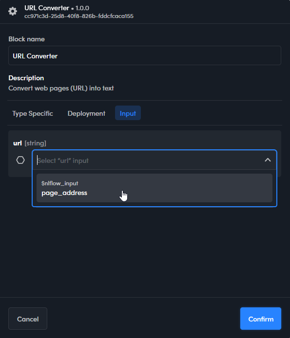
In the reference section of this manual you will find the description of the input properties for models, processors and operators.
To define the workflow input format, select the ellipsis  then Input format definition. The Input format definition window appears.
![]()
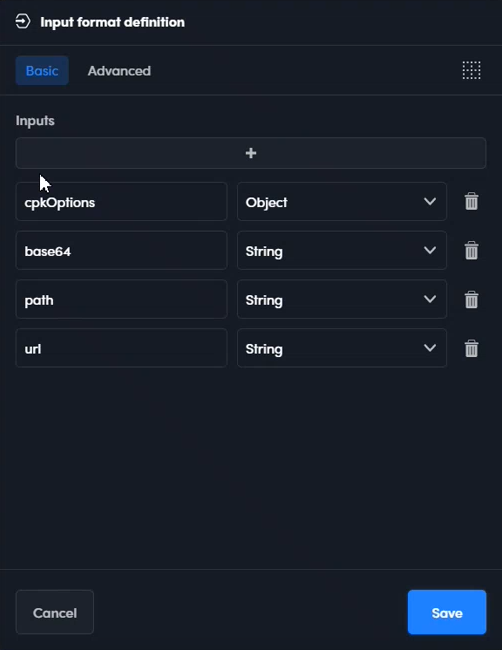
Use the Basic tab to define the format interactively:
- To define a new top level key, select the plus button
 . A couple of boxes appears below the list. Enter the name of the new key in the left box and click elsewhere, then select the key type from the drop-down box on the right.
 - To modify a key change its name and/or type.
- To delete a key select it and then select Delete

Alternatively, use the text editor in Advanced tab to define the format by writing a JSON template.
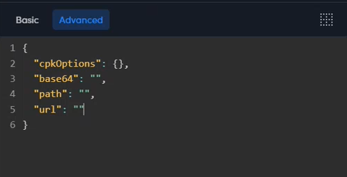
The entire template must be enclosed in curly braces. The syntax of the definition for a key is:
"keyName": keyType
where keyName is the name of the key. keyType represents the type of the key and can be:
{}for an object[]for an array""for a string0for a numberfalsefor a boolean
Use the comma , to separate multiple keys.
To delete all the keys select Clear text  .
.
To save the definition select Save.
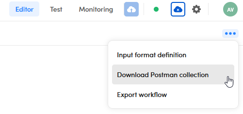
Download the Postman collection
To download a Postman collection with which you can test a published workflow through the Workflow API, select the ellipsis then Download Postman collection.
Once you have imported the collection into Postman, for each request you must set the X-API-KEY header with the value of the API key associated with the published workflow.
Export the workflow
To export the workflow, select the ellipsis then Export workflow.
Upload a model
To upload a Symbolic model or a ML model, select  in the left panel.
Note
It is possible to upload a model also in the Models view.